Download presentation
Presentation is loading. Please wait.

1
5-12 LCM顯示控制實習 SW2 P P1 8051

2
Program function (範例) Program 5_12_1: 。 Program 5_12_2:。
Program 5_12_6: 在LCM的中間位置,以00:00:00的格式來顯示一電子馬錶的內容,其中最左邊二位數代表「分」,中間二位數代表「秒」,並以0.01秒的解析度來計時,當按下鍵盤的「 1」代表開始或繼續計時,按下鍵盤的「 2」代表暫停計時,按下鍵盤的「 0」則作歸零的動作。

3
Program function (自我練習)
")
4
LCM & 8051 interface Pin # Name Function 1 VSS Ground 2 VDD +5 V 3 VO
反襯度調整。 4 RS Selects registers. 0: Instruction register (for write) Busy flag: address counter (for read) 1: Data register (for write and read) 5 R/W Selects read or write. 0: Write 1: Read 6 EN Starts data read/write. 7~14 DB0~DB7 for data transfer and receive
 Busy flag: address counter (for read) 1: Data register (for write and read) 5. R/W. Selects read or write. 0: Write. 1: Read. 6. EN. Starts data read/write. 7~14. DB0~DB7. for data transfer and receive.")
5
HD44780U (LCD Controller/Driver) Block Diagram
8051 P1 P0 Source of figure:

6
Connections between HD44780 & LCD
8051 P1 P0

7
Connections among 8051, HD44780, & LCD

9
LCM之組成單元 組成單元(1) Instruction register (IR)
組成單元(2) Display data RAM (DDRAM) 80 8 bits 00H 01H 02H 03H 10H 11H 12H 13H 40H 41H 42H 43H 50H 51H 52H 53H
 Display data RAM (DDRAM) 80 8 bits. 00H. 01H. 02H. 03H. 10H. 11H. 12H. 13H. 40H. 41H. 42H. 43H. 50H. 51H. 52H. 53H.")
10
LCM之組成單元 組成單元(3) Character generator ROM (CGROM) 9,920 bits
組成單元(4) Character generator RAM (CGRAM) 64 bytes
 Character generator RAM (CGRAM) 64 bytes.")
11
LCM之組成單元 組成單元(5) Data register (DR) 組成單元(6) Address counter (AC)
 Data register (DR) 組成單元(6) Address counter (AC)")
12
LCM之組成單元 組成單元(7) Busy flag (BF) 組成單元(8) Timing generator
 Busy flag (BF) 組成單元(8) Timing generator")
13
LCM之組成單元 組成單元(9) Cursor and blink controller 組成單元(10) Bias generator
 Cursor and blink controller 組成單元(10) Bias generator")
14
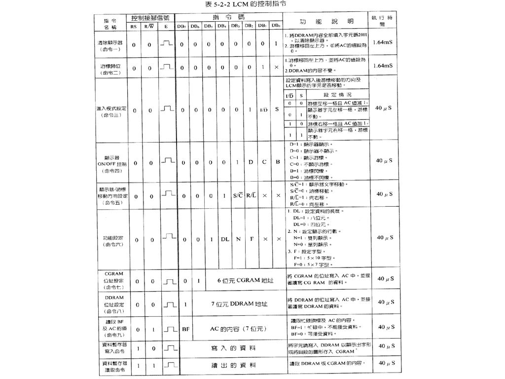
LCM控制指令 指令名稱 控制接腳信號 指令碼 功能說明 執行時間 RS R/W E DB7 DB6 DB5 DB4 DB3 DB2 DB1
清除顯示器 1 游標歸位 進入模式設定 ON/OFF控制 顯示器 /游標移動方向設定 S/C R/L 功能設定 CGRAM位址設定 DDRAM位址設定 讀取BF及AC的值 資料暫存器寫入命令 寫入的資料 資料暫存器讀取命令 讀取的資料

15
指令一、二 指令名稱 控制接腳信號 指令碼 功能說明 執行時間 RS R/W E DB7 DB6 DB5 DB4 DB3 DB2 DB1
命令一 清除顯示器 ┌┐ 1 1. Clear the display by filling DDRAM with 20H’s. 2. Move the cursor to the upper left corner; Clear AC. 1.64 ms 此命令將DDRAM內容全設為20H,以清除LCM顯示。空白字的字元碼就是20H。 將AC設為0可使游標移到第一行第一列。 命令二 游標歸位 x Move the cursor to the upper left corner; Clear AC. (The DDRAM content doesn’t change.) 此命令只是把AC設為0,以便將游標移到第一行第一列。 DDRAM的內容沒有受到改變,所以文字照樣顯示。
 此命令只是把AC設為0,以便將游標移到第一行第一列。 DDRAM的內容沒有受到改變,所以文字照樣顯示。")
16
指令三、四 指令名稱 控制接腳信號 指令碼 功能說明 執行時間 RS R/W E DB7 DB6 DB5 DB4 DB3 DB2 DB1
命令三 進入模式設定 ┌┐ 1 I/D S Determine the cursor direction after writing in the data; Determine whether the displayed character will move 40 s Cursor shifts left. AC = AC 1. Character shifts left. Cursor doesn’t move Cursor shifts right. AC = AC + 1. Character shifts right. Cursor doesn’t move I/D = 1: 命令四 顯示器ON/OFF控制 D C B D = 1:display D = 0:does not display D = 1:show cursor D = 0:does not show cursor D = 1:cursor blinks D = 0:cursor doesn’t blink 此命令控制(1) 文字是否顯示、(2)游標是否顯示、(3)游標是否閃爍。 例如:指令碼 0FH 顯示文字、顯示游標、游標閃爍。 交互使用指令碼 08H 和 0CH 文字閃爍。
 文字是否顯示、(2)游標是否顯示、(3)游標是否閃爍。 例如:指令碼 0FH 顯示文字、顯示游標、游標閃爍。 交互使用指令碼 08H 和 0CH 文字閃爍。")
17
指令五、六 指令名稱 控制接腳信號 指令碼 功能說明 執行時間 RS R/W E DB7 DB6 DB5 DB4 DB3 DB2 DB1
命令五 設定顯示器/游標移動方向 ┌┐ 1 S/C R/L S/C = 1: shift the displayed text S/C = 0: shift the cursor R/L = 1: shift left R/L = 0 shift right 40 s 命令六 功能設定 DL N F x

18
指令七、八、九 指令名稱 控制接腳信號 指令碼 功能說明 執行時間 RS R/W E DB7 DB6 DB5 DB4 DB3 DB2 DB1
命令七 位址設定 ┌┐ 1 CGRAM address (6 bits) 40 s 命令八 DDRAM address (7 bits) Write AC with DDRAM address 命令九 讀取BF和AC的值 BF AC content (7 bits)
 40 s. 命令八. DDRAM address (7 bits) Write AC with DDRAM address. 命令九. 讀取BF和AC的值. BF. AC content (7 bits)")
19
指令、 指令名稱 控制接腳信號 指令碼 功能說明 執行時間 RS R/W E DB7 DB6 DB5 DB4 DB3 DB2 DB1 DB0
資料暫存器寫入命令 1 ┌┐ 寫入的資料 40 s 資料暫存器讀取命令 讀出的資料

23
LCM初始化 (1) 電源重置
 電源重置")
24
LCM初始化 (2) 軟體重置
 軟體重置")
25
5-12-1 LCM文字顯示控制 (一) 程式功能: 在LCM第一列中央顯示”Hello! Welcome”。
comment 程式功能: 在LCM第一列中央顯示”Hello! Welcome”。 * 使用LCM前應先做初始化。 * 送資料和下命令給LCM前應先檢查LCM是否已忙完了。

26
Program 5_12_1 (1/3) RS REG P1.5 ; (p.103) 虛擬指令REG: 以一名稱代表一個暫存器或直接定址位元。 RW REG P1.6 EN REG P1.7 LCMBUS REG P0 ;============================== ORG H MOV SP,#60 CLR EN CALL LCMINIT MOV A,# B ; These two instruction accomplish a 命令八. The instruction code is B . CALL WRINS ; The last 7 bits is to be loaded into AC to be used as the DDRAM address. ; The effect is to move the cursor to the top leftmost location of the LCM. MOV DPTR,#LINE CALL PRTSTR JMP $ LINE DB " Hello! Welcome $“ Excerpt from I5_12_1.LST: LINE DB " Hello! Welcome $" 006A 6C 6C 6F 21 20 006F C 63 6F D

27
Program 5_12_1 (2/3) ;==============================
; Function: Wait until BF = 0 ; Algorithm: ; * Use 命令九 to acquire BF; ; * Keep acquiring and checking value of BF ; when BF stays at 1 ; * Return when BF becomes 0. ; CHKBSY: MOV LCMBUS,#0FFH ; To use P0 as an input port CLR RS ; RS = 0 SETB RW ; RW = 1. 命令九 SETB EN MOV C,LCMBUS ; = BF CLR EN JC CHKBSY ; Jump if BF = 1 RET ; Return if BF = 0 ;==============================t ;============================== ; 命令一 ~ 八都有可能,視Acc的內容而定。 ; Input: A = the instruction code ; WRINS: CALL CHKBSY CLR RS ; RS = 0 CLR RW ; RW = 0 SETB EN MOV LCMBUS,A CLR EN RET ;============================== ; Function: to display an ASCII string pointed to by DPTR until a ‘$’ ; Input: DPTR points to the ASCII string to be displayed. ; PRTSTR: MOV A,#0 MOVC CJNE A,#'$',PRINT JMP ENDPRT PRINT: CALL WRDATA INC DPTR JMP PRTSTR ENDPRT: RET ;============================== ; Display a character contained in Acc ; Input: A = ASCII code of the character to ; be displayed ; WRDATA: CALL CHKBSY SETB RS ; RS = 1 CLR RW ; RW = 0 SETB EN MOV LCMBUS,A CLR EN RET

28
Quiz: In the routine WRINS, which LCM control instruction is executed
Quiz: In the routine WRINS, which LCM control instruction is executed? How do you know? Ans: Because RS = 0 and RW = 0, one among 命令一 ~ 八will be executed. The value in the accumulator will determine which of these eight instructions will be executed. Quiz: In the routine CHKBSY, how do you know that 命令九 is used? Ans: Quiz: Is the first instruction {MOV LCMBUS,#0FFH} in CHKBSY an LCM instruction? Why? Ans: It is not, because the LCM has not been enabled when this instruction is executed. Quiz: In the routine CHKBSY, what is the purpose of the first instruction {MOV LCMBUS,#0FFH}?

29
Program 5_12_1 (3/3) ;==============================
; Initialize the LCM. ; LCMINIT: MOV A,# B CALL WRINS MOV R6,#41 ;DELAY 4.1mS $1: MOV R7,#50 DJNZ R7,$ DJNZ R6,$1 MOV R7,#50 ;DELAY 100uS MOV A,# B ;FUNCTION SET MOV A,# B ;DISPLAY OFF MOV A,# B ;DISPLAY CLEAR CALL WRINS MOV A,# B ;ENTRY MODE SET MOV A,# B RET

30
5-12-2 LCM文字顯示控制 (二) 程式功能: 在LCM第一列中央顯示”Hello! Welcome”,
並以0.5秒的時間間隔做閃爍。 * 此程式使用命令四造成文字閃爍的視覺效果。

31
Program 5_12_2 RS REG P1.5 RW REG P1.6 EN REG P1.7 LCMBUS REG P0
;============================== ORG H MOV SP,#60 CLR EN CALL LCMINIT MOV A,# B ;SET DDRAM ADDRESS = 00H CALL WRINS MOV DPTR,#LINE CALL PRTSTR LINE DB “ Hello! Welcome $” 將 Program 5_12_1的 JMP $ 指令改成左列的指令,就達到閃爍的目的。 NEXT: CALL DELAY MOV A,# B ; 08H CALL WRINS ; 命令四,DISPLAY OFF MOV A,# B ; 0CH CALL WRINS ; 命令四,DISPLAY ON JMP NEXT (in Program 5_12_1) JMP $
 JMP $")
32
LCM文字顯示控制 (三) 程式功能:將文字串”Hello! Welcome”由LCM右側往左緩慢移入到第一列的中央位置,然後不斷閃爍。 * 此程式比前兩小節(5-12-1, )程式多加兩個副程式,即FLASH和SHIFT。
程式多加兩個副程式,即FLASH和SHIFT。 .")
33
Program I5_12_3.asm 之主程式 RS REG P1.5 RW REG P1.6 EN REG P1.7
comment RS REG P1.5 RW REG P1.6 EN REG P1.7 LCMBUS REG P0 ;=========================== .SYMBOLS ON ORG 0000H JMP MAIN ORG 0050H MAIN: MOV SP,#60 CLR EN ;DISABLE LCM CALL LCMINIT MOV A,# B ;SET DDRAM ADDRESS = 14H CALL WRINS MOV DPTR,#LINE ;DISPLAY STRING CALL PRTSTR MOV R1,#17 ;Totally 17 characters NEXT: CALL SHIFT CALL DELAY DJNZ R1,NEXT N_FLASH: CALL FLASH JMP N_FLASH LINE DB "Hello! Welcome $“ ;==============================

34
Program I5_12_3.asm 增加之副程式 ;==============================
; 用命令四造成文字閃爍的效果。 ; 與Program 5_12_2的NEXT後那一段程式相同。 ; FLASH: CALL DELAY MOV A,# B ; Text display OFF CALL WRINS MOV A,# B ; Text display ON RET ;============================== ; 用命令五,S/C = 1 移動顯示的文字, R/L = 0 向左移 ; SHIFT: MOV A,# B ; Displayed text shift left CALL WRINS RET

35
5-12-4 LCM文字顯示控制 (四) 程式功能:將矩陣鍵盤所按的鍵值顯示在LCM上並有閃爍的游標。
此程式比前三小節多增加一個副程式RDINS以讀取指令暫存器(IR)的內容。此副程式用命令九讀取AC (Address counter)的內容,以判斷游標的位置是否已經到了一列的最右邊。 若游標已超過第一列的最右邊(13H),必須將之移到第二列的最左邊。 若游標已超過第二列的最右邊(53H),必須將之移到第一列的最左邊。 Key code 必須先轉成 ASCII code 才能送到LCM顯示。 Key code = 0 ~ 9 ASCII code = key code + 30H Key code = A ~ F ASCII code = key code + 37H
的內容。此副程式用命令九讀取AC (Address counter)的內容,以判斷游標的位置是否已經到了一列的最右邊。 若游標已超過第一列的最右邊(13H),必須將之移到第二列的最左邊。 若游標已超過第二列的最右邊(53H),必須將之移到第一列的最左邊。 Key code 必須先轉成 ASCII code 才能送到LCM顯示。 Key code = 0 ~ 9 ASCII code = key code + 30H. Key code = A ~ F ASCII code = key code + 37H.")
36
Pprogram I5_12_4.ASM (1/3: main program)
RS REG P1.5 RW REG P1.6 EN REG P1.7 LCMBUS REG P0 ;============================== .SYMBOLS ON ORG 0000H JMP MAIN ORG 003H JMP INT0 ORG 100H MAIN: MOV SP,#60 MOV P1,#0FFH MOV IE,# B SETB IT0 CLR EN CALL LCMINIT MOV A,# B ;SET DDRAM ADDRESS CALL WRINS JMP $ comment

37
Pprogram I5_12_4.ASM (2/3: INT0 service routine)
;============================== INT0: CLR EA CLR C MOV A,P1 ANL A,#0FH MOV B,A ; To convert key code into ASCII code. SUBB A,# ; If A < 10, then A is 0 ~ 9 JC NUMBER ; MOV A,B ; A is A ~ F ADD A,#37H ; ASCII code = A + 37H JMP DISP ; NUMBER: ; MOV A,B ; A is 0 ~ 9 ADD A,#30H ; ASCII code = A + 30H DISP: CALL WRDATA CALL RDINS ANL A,# B MOV B,A SUBB A,#14H ; To determine if the cursor is at the end of the 1st row JNZ TESTB MOV A,# B ; Move the cursor to the beginning of the 2nd row CALL WRINS TESTB: MOV A,B SUBB A,#54H ; To determine if the cursor is at the end of the 2nd row JNZ RETURN MOV A,# B ; Move the cursor to the beginning the 1st row RETURN: SETB EA RETI comment

38
Pprogram I5_12_4.ASM (2/3: INT0 service routine)
comment Key Key code ASCII code Key code 00H 30H 1 01H 31H 2 02H 32H 3 03H 33H 4 04H 34H 5 05H 35H 6 06H 36H 7 07H 37H 8 08H 38H 9 09A 39H A 0AH 41H B 0BH 42H C 0CH 43H D 0DH 44H E 0EH 45H F 0FH 46H How to determine if the key code is among 0 ~ 9 or A ~ F: If the key code – 10 < 0, then the key code is among 0 ~ 9 and ASCII code = key code + 30H If the key code – 10 >= 0, then the key code is among A ~ F and ASCII code = key code + 37H

39
Program I5_12_4.ASM (3/3: subroutine)
;============================== ; 用命令九讀取AC內容。 ; Input: none. ; Output: Acc (the accumulator) contains BF and AC. ; RDINS: CALL CHKBSY CLR RS ; RS = 0 SETB RW ; RW = 1 SETB EN MOV A,LCMBUS CLR EN RET Quiz: How do you know that the subroutine RDINS uses 命令九? Ans: ;============================== ; 其他副程式包括 ; WRINS, ; WRDATA, ; CHKBSY, ; LCMINIT, ; PRTSTR ; 其內容和前幾個小節的副程式一樣,
 contains BF and AC. ; RDINS: CALL CHKBSY. CLR RS ; RS = 0. SETB RW ; RW = 1. SETB EN. MOV A,LCMBUS. CLR EN. RET. Quiz: How do you know that the subroutine RDINS uses 命令九? Ans: ;============================== ; 其他副程式包括. ; WRINS, ; WRDATA, ; CHKBSY, ; LCMINIT, ; PRTSTR. ; 其內容和前幾個小節的副程式一樣,")
40
comment

41
LCM文字顯示控制 (五) 程式功能: * 此程式
 程式功能: * 此程式")
42
comment

43
comment

44
六位數字電子碼錶 程式功能: * 此程式

45
comment

46
comment

47
comment

48
comment

Similar presentations


 XRL (2) EQU (3) MACRO (4) ORG.>")


 4.1 引言 4.2 逻辑设计的一般方法 4.3 建立数据通路 4.4 一个简单的实现机制 4.5 多周期实现机制.>")


 按权展开,除x取余 2>")