Download presentation
Presentation is loading. Please wait.

1
絕緣電阻測試 insulation resistance testing
Lecture 03 絕緣電阻測試 insulation resistance testing

2
何時需要測量絕緣電阻: 製造完成後第一次使用 新設備安裝完成送電前 在工作壽命中定期檢驗 維修完成送電前 長時間停機之後,再重新使用送電前 造成絕緣退化的原因: 電力的應力—例如:過電壓造成的絕緣穿刺。 機械的應力—例如:震動或撞擊造成的破壞。 化學侵蝕—例如:灰塵,油漬或腐蝕性的氣體等。 溫度的影響—例如:過冷過熱的變動,或長時間過載使用。 環境的影像—例如:蟲害或濕度太高的環境等。

3
測量電氣設備的絕緣電阻之目的: 影響絕緣電阻測量值的因素有: 溫度 濕度 測量電壓 作用時間 繞組中殘存電荷 絕緣的表面狀況等
瞭解絕緣結構的絕緣性能;從由優質絕緣材料組成合理的絕緣結構或絕緣系統,應該具有良好的絕緣性能和較高的絕緣電阻值。 瞭解電器產品絕緣性能狀況;電器產品絕緣處理不佳,其絕緣性能將明顯下降。 瞭解絕緣受潮及受污染情況;當電氣設備的絕緣受潮及受污染後,其絕緣電阻通常會明顯下降。 檢驗絕緣是否承受耐電壓試驗;若在電氣設備的絕緣電阻低於某一限值時進行耐電壓測試,將會產生較大的試驗電流,造成熱擊穿而損壞電氣設備的絕緣。因此,通常各式各樣試驗標準均規 定在耐電壓試驗前,先測量絕緣電阻。 影響絕緣電阻測量值的因素有: 溫度 濕度 測量電壓 作用時間 繞組中殘存電荷 絕緣的表面狀況等

4
R=V/I , where is the current from?
Total leakage current : Conductive leakage current (IL ) Capacitive charging leakage current (IC ) Polarization absorption leakage current (IA ) Surface Leakage current (Is) 測量開始後一分鐘: I= IL+ IA+ Is 測量開始後十分鐘: I= IL+ Is
 Capacitive charging leakage current (IC ) Polarization absorption leakage current (IA ) Surface Leakage current (Is) 測量開始後一分鐘: I= IL+ IA+ Is. 測量開始後十分鐘: I= IL+ Is.")
5
介質吸收 現象 對設備之絕緣加一穩定的DC電壓測定通過迴路之總電流,此電流分成三成份:
洩漏電流 (用來衡量絕緣物絕緣電阻的電流) 介質吸收電流 電容充電電流 其中洩漏電流值占絕大部份。如圖曲線A及B。 曲線B平直表示絕緣層含有水份或汙物附著而減低內部電阻。 曲線A具有急陡之曲線表示含水份少、汙物少、絕緣性能良好。 Absorption current (介質吸收電流) is caused by the polarization of molecules within dielectric material. In low-capacitance equipment, the current is high for the first few seconds and decreases slowly to nearly zero. When dealing with high capacitance equipment or wet and contaminated insulation, there will be no decrease in the absorption current for a long time.
 介質吸收電流. 電容充電電流. 其中洩漏電流值占絕大部份。如圖曲線A及B。 曲線B平直表示絕緣層含有水份或汙物附著而減低內部電阻。 曲線A具有急陡之曲線表示含水份少、汙物少、絕緣性能良好。 Absorption current (介質吸收電流) is caused by the polarization of molecules within dielectric material. In low-capacitance equipment, the current is high for the first few seconds and decreases slowly to nearly zero. When dealing with high capacitance equipment or wet and contaminated insulation, there will be no decrease in the absorption current for a long time.")
6
絕緣電阻測試方法: Spot Reading Test (趨勢圖) Polarization Index (PI 極化指數) Dielectric Absorption Ratio (DAR 介質吸收比) Step Voltage (步級電壓) Dielectric Discharge (介質放電)
 Dielectric Discharge (介質放電)")
7
Spot Reading Test Method For this test, the megohmmeter is connected across the insulation of the windings of the machine being tested. A test voltage is applied for a fixed period of time, usually 60 seconds and a reading is taken. The spot reading test should only be carried out when the winding temperature is above the dew point (1). The operator should make a note of the winding temperature, so that it will be possible to correct the reading to a base temperature of 20 ℃. (1) Dew point temperature is the temperature at which the moisture vapor in the air condenses as a liquid. Test Duration To obtain comparable results, tests must be of the same duration. Usually the reading is taken after 60 seconds. Interpretation of Results Proper interpretation of spot reading tests requires access to records of results from previous spot reading tests. For conclusive results, only use results from tests performed at the same test voltage for the same amount of time, and under similar temperature and humidity conditions. These readings are used to plot a curve of the history of insulation resistance. A curve showing a downward trend usually indicates a loss of insulation resistance due to unfavorable conditions such as: humidity, dust accumulation, etc. A very sharp drop indicates an insulation failure. See Figure 1.
. The operator should make a note of the winding temperature, so that it will be possible to correct the reading to a base temperature of 20 ℃. (1) Dew point temperature is the temperature at which the moisture vapor in the air condenses as a liquid. Test Duration To obtain comparable results, tests must be of the same duration. Usually the reading is taken after 60 seconds. Interpretation of Results Proper interpretation of spot reading tests requires access to records of results from previous spot reading tests. For conclusive results, only use results from tests performed at the same test voltage for the same amount of time, and under similar temperature and humidity conditions. These readings are used to plot a curve of the history of insulation resistance. A curve showing a downward trend usually indicates a loss of insulation resistance due to unfavorable conditions such as: humidity, dust accumulation, etc. A very sharp drop indicates an insulation failure. See Figure 1.")
8
Example of the variation of insulation resistance over a period of years: A, 絕緣電阻漸漸下降,代表絕員可能老化或受到塵埃汙染。 B, 絕緣電阻尖銳的驟降點代表絕緣破壞。 C, 馬達線圈重繞處理後絕緣電阻回升。

9
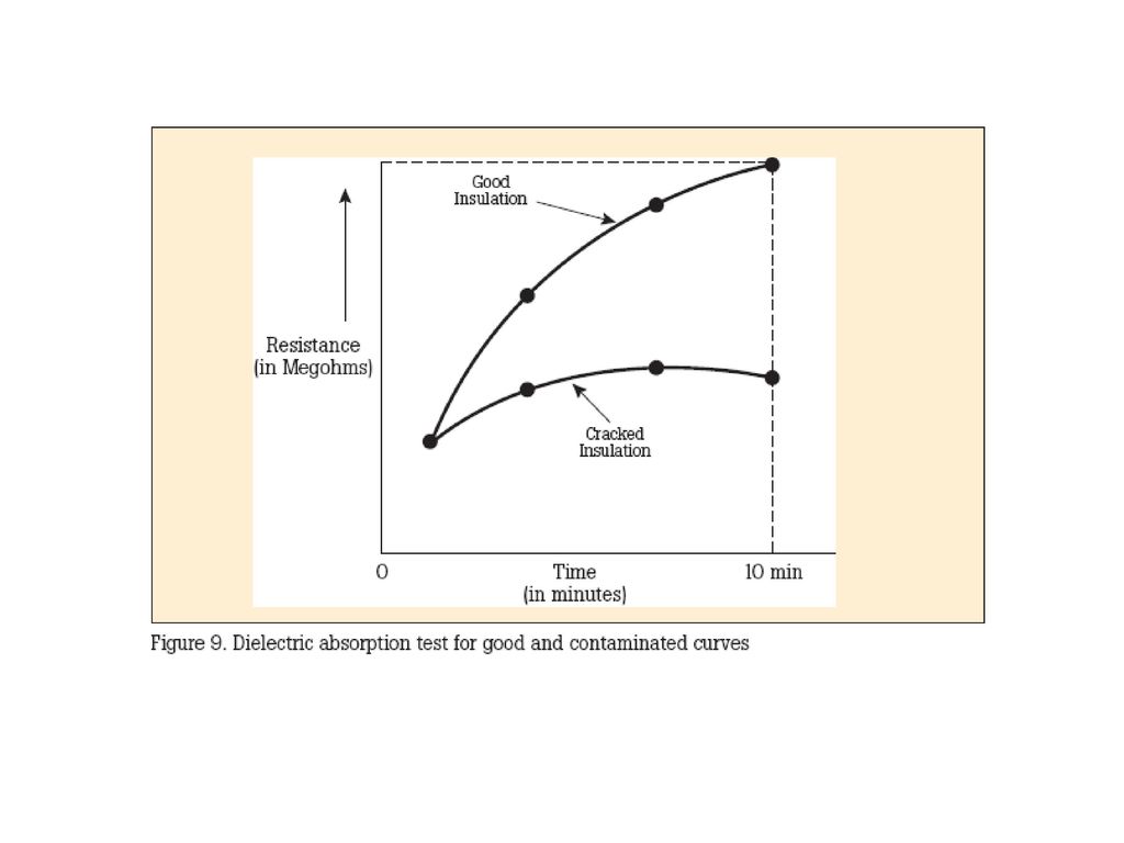
Dielectric Absorption Ratio (DAR) or Time-Resistant Tests
This method is fairly independent of temperature and often can give you conclusive information without records of past tests. It is based on the absorption effect of good insulation compared to that of moist or contaminated insulation. Simply take successive readings at specific times and note the differences in readings (see curves, Figure 2). Tests by this method are sometimes referred to as absorption tests. Good insulation shows a continual increase in resistance (see curve D) over a period of time (in the order of 5 to 10 minutes). This is caused by the absorption; good insulation shows this charge effect over a time period much longer that the time required to charge the capacitance of the insulation. If the insulation contains moisture or contaminants, the absorption effect is masked by a high leakage current which stays at a fairly constant value Ð keeping the resistance reading low (R = E/I) (see curve E). The time-resistance testing is of value because it is independent of equipment size. The increase in resistance for clean and dry insulation occurs in the same manner whether a motor is large or small. You can compare several motors and establish standards for new ones, regardless of their horsepower ratings.
. Tests by this method are sometimes referred to as absorption tests. Good insulation shows a continual increase in resistance (see curve D) over a period of time (in the order of 5 to 10 minutes). This is caused by the absorption; good insulation shows this charge effect over a time period much longer that the time required to charge the capacitance of the insulation. If the insulation contains moisture or contaminants, the absorption effect is masked by a high leakage current which stays at a fairly constant value Ð keeping the resistance reading low (R = E/I) (see curve E). The time-resistance testing is of value because it is independent of equipment size. The increase in resistance for clean and dry insulation occurs in the same manner whether a motor is large or small. You can compare several motors and establish standards for new ones, regardless of their horsepower ratings.")
10
Figure 2 shows how a 60-second test would appear for good and bad insulation. When the insulation is in good shape, the 60-second reading is higher that the 30-second reading. A further advantage of this two reading test is that it gives you a clearer picture, even when a “spot reading” says the insulation looks ok. Time-resistance tests on large rotating electrical machinery - especially with high operating voltage - require high insulation resistance ranges and a very constant test voltage. A heavy-duty megohmmeter serves this need. Similarly, such an instrument is better adapted for cables, bushings, transformers, and switchgear in the heavier-duty sizes. DAR Test Methods DAR =R(60 sec)/R(30 sec) less than 1 = failed 1.0 to 1.25 = OK 1.4 to 1.6 = excellent Note: This is not a commonly used test
/R(30 sec) less than 1 = failed. 1.0 to 1.25 = OK. 1.4 to 1.6 = excellent. Note: This is not a commonly used test.")
11
polarization index (PI)
Absorption curve of test conducted on 350 HP Motor: Curve D indicates a good insulation with an excellent polarization index of 5. Curve E indicates a potential problem. The polarization index is only 140/95, or 1.47.

13
步級電壓測試

14
步級電壓測試 Before and after repair: Curve F顯示當測試電壓上升時絕緣電阻呈現下降的趨勢. 這表示絕緣物有潛在的絕緣不良的問題. Curve G 顯示相同設備在絕緣修復之後的情況,絕緣電阻不會因為測試電壓上升而有明顯的下降情況。

15
R=V/I , How many volts? Voltage Level IR Tester 650V 500V DC 1.1KV
1KV DC 3.3KV 2.5KV DC 66Kv and Above 5KV DC MEGGER FLUCK 絕緣阻抗的測試與耐壓測試其接線方式大致相同,主要是量測兩個端點之間及其週邊連接在一起的各項關聯網路所形成的等效電阻值, 絕緣電阻是指用絕緣材料隔開兩部分導體之間的電阻稱絕緣電阻,為確保電氣設備運行的安全,對其不同極性(不同相)的導電體之間,或導電體與外殼之間的絕緣電阻均須滿足一定的要求。 屏蔽端子
的導電體之間,或導電體與外殼之間的絕緣電阻均須滿足一定的要求。 屏蔽端子.")
16
屏蔽端子的使用 Rc: 電纜絕緣體絕緣電阻 Rs: 外層洩漏電阻 Rn: 線路其他高壓設備絕緣電阻

17
使用前,首先要做好以下各種準備: (1)測量前必須將被測設備電源切斷,並對地短路放電,決不允許設備帶電進行測量,以保證人身和設備的安全。 (2)對可能感應出高壓電的設備,必須消除這種可能性后,才能進行測量。 (3)被測物表面要清潔,減少接觸電阻,確保測量結果的正確性。 (4) 測量前要檢查儀器是否處於正常工作狀態,主要檢查其「0」和「∞」兩點。兆歐表即搖動手柄,使電機達到額定轉速,兆歐表在短路時應指在「0」位置,開路時應指在「∞」位置。 (5)儀器應放在平穩、牢固的地方,且遠離大的外電流導體和外磁場。做好上述準備工作后就可以進行測量了,在測量時,還要注意正確接線,否則將引起不必要的誤差甚至錯誤。
被測物表面要清潔,減少接觸電阻,確保測量結果的正確性。 (4) 測量前要檢查儀器是否處於正常工作狀態,主要檢查其「0」和「∞」兩點。兆歐表即搖動手柄,使電機達到額定轉速,兆歐表在短路時應指在「0」位置,開路時應指在「∞」位置。 (5)儀器應放在平穩、牢固的地方,且遠離大的外電流導體和外磁場。做好上述準備工作后就可以進行測量了,在測量時,還要注意正確接線,否則將引起不必要的誤差甚至錯誤。")
18
屋內線路裝置規則 第19條 低壓電路之絕緣電阻應符合左列規定之一辦理: 一、除左列各目之規定外,低壓電路之導線間及導線與大地之絕緣電阻(多心電纜或多心導線係心線相互間及心線與大地之絕緣電阻),於進屋線、幹 線或分路之開關切開,測定電路絕緣電阻,應有表一九之規定值以上。冬雨及鹽害嚴重地區,裝置兩年以上電燈線路絕緣電阻不得低於○‧○五MΩ。 (一)符合第十八條(電路之絕緣)規定之須接地部分。 (二)符合第七款及第八款規定之起重機或遊樂用電車部分。 (三)旋轉機及整器之流電路。 (四)符合第二十一條(變壓器之絕緣耐壓)規定之變壓器部分。 (五)開關、過電流保護設備、電容器、感應電壓整器、變比器及其他器具及裝設於變電所或電廠機器之接線及匯流排之電路。 二、「低壓導線間之絕緣電阻」應為切開電機器具狀態包括低壓屋內線,移動電線及電燈之燈具線等之線間絕緣電阻,但不包括電機器具內之電路。 三、「低壓電路之導線與大地之統緣電阻」應為低壓屋內線、移動電線及電機器具內之電路與大地之絕緣電阻,即電機器具在使用狀態所測定之電路與大地之絕緣電阻。 四、新設時絕緣電阻,建議在一MΩ以上。 五、既設線路之定期或非定期絕緣測定,可免導線相互間之絕緣電阻測定。自接戶線至接戶開關絕緣電阻測定有困難者,得免測定。 六、低壓電路之絕緣電阻測定應使用六○○伏額定及二五○伏額定(二二○伏以下電路用)之絕緣電阻計。 七、升降機、起重機及類似可移動式機器,使用滑行導線供電者(除三○○伏以下,採用絕緣導線或由一次電壓三○○伏以下之絕緣變壓器供電或接地電阻一○Ω以下者外),導線與大地之絕緣電阻應保持表一九之規定值以上。新設時之絕緣電阻,建議在一MΩ以上。 八、遊樂用電車之電源,接觸導線及電車內部電路與大地之絕緣電阻,應符合左列規定: (一)接觸導線每一公里之漏電電流,在使用電壓情形下,不得超過○‧一安(一○○毫安)。 (二)電車內部電路之漏電電流,在使用電壓情形下不得大於其額定電流之五千分之一。 九、屋外配線,絕緣導線與大地之絕緣電阻(多心電纜或多心電線,心線之相互間及心線與大地之絕緣電阻)在額定電壓情形下,各導線之漏電電流不 得大於額定電流之二千分之一。單相二線式電路,非接地導線與大地之絕緣電阻,在額定電壓情形下漏電電流不得大於額定電流之二千分之一。
,於進屋線、幹 線或分路之開關切開,測定電路絕緣電阻,應有表一九之規定值以上。冬雨及鹽害嚴重地區,裝置兩年以上電燈線路絕緣電阻不得低於○‧○五MΩ。 (一)符合第十八條(電路之絕緣)規定之須接地部分。 (二)符合第七款及第八款規定之起重機或遊樂用電車部分。 (三)旋轉機及整器之流電路。 (四)符合第二十一條(變壓器之絕緣耐壓)規定之變壓器部分。 (五)開關、過電流保護設備、電容器、感應電壓整器、變比器及其他器具及裝設於變電所或電廠機器之接線及匯流排之電路。 二、「低壓導線間之絕緣電阻」應為切開電機器具狀態包括低壓屋內線,移動電線及電燈之燈具線等之線間絕緣電阻,但不包括電機器具內之電路。 三、「低壓電路之導線與大地之統緣電阻」應為低壓屋內線、移動電線及電機器具內之電路與大地之絕緣電阻,即電機器具在使用狀態所測定之電路與大地之絕緣電阻。 四、新設時絕緣電阻,建議在一MΩ以上。 五、既設線路之定期或非定期絕緣測定,可免導線相互間之絕緣電阻測定。自接戶線至接戶開關絕緣電阻測定有困難者,得免測定。 六、低壓電路之絕緣電阻測定應使用六○○伏額定及二五○伏額定(二二○伏以下電路用)之絕緣電阻計。 七、升降機、起重機及類似可移動式機器,使用滑行導線供電者(除三○○伏以下,採用絕緣導線或由一次電壓三○○伏以下之絕緣變壓器供電或接地電阻一○Ω以下者外),導線與大地之絕緣電阻應保持表一九之規定值以上。新設時之絕緣電阻,建議在一MΩ以上。 八、遊樂用電車之電源,接觸導線及電車內部電路與大地之絕緣電阻,應符合左列規定: (一)接觸導線每一公里之漏電電流,在使用電壓情形下,不得超過○‧一安(一○○毫安)。 (二)電車內部電路之漏電電流,在使用電壓情形下不得大於其額定電流之五千分之一。 九、屋外配線,絕緣導線與大地之絕緣電阻(多心電纜或多心電線,心線之相互間及心線與大地之絕緣電阻)在額定電壓情形下,各導線之漏電電流不 得大於額定電流之二千分之一。單相二線式電路,非接地導線與大地之絕緣電阻,在額定電壓情形下漏電電流不得大於額定電流之二千分之一。")
19
Q:如何量測以下低壓配電盤之絕緣電阻?

20
Ans: 低壓配電盤 線間絕緣電阻測量 低壓電路之導線間及導線對大地之間的最低絕緣電阻應符合下表之規定: 線路電壓 絕緣電阻 (MΩ)
300V 以下 對地電壓150V以下 0.1 對地電壓150V以上 0.2 300V 以上 0.4 Ans: 低壓配電盤 線間絕緣電阻測量 燈 插座

21
Ans: 低壓配電盤 導線與大地絕緣電阻測量
燈 插座

22
低壓馬達 繞組絕緣電阻測量

23
個人防護用品包括防護服、頭部、眼睛、耳朵、手和腳,背部、膝部防護用品,以及橡膠絕緣墊。

Similar presentations


 接地工程 主講人:王廷興 博士 台北科技大學冷凍空調系 副教授>")


>")


>")


